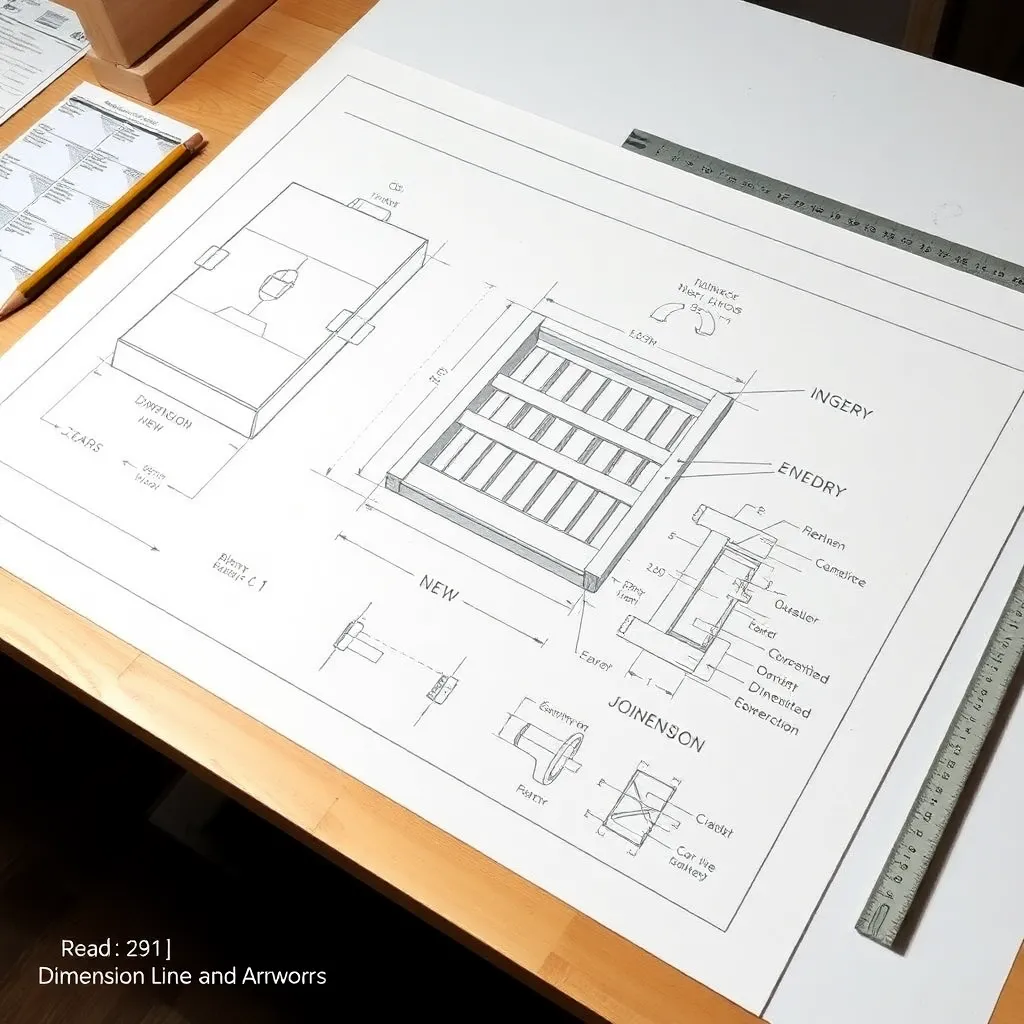
Every woodworking plan — whether from a magazine, a website, or Ted’s Woodworking’s library — uses a set of standard symbols and conventions. Builders who can read these symbols get to work immediately; builders who can’t spend half their project time interpreting what the plan is asking. This guide covers every symbol you’ll encounter: dimension lines, joinery callouts, section views, exploded views, and hardware notations.
Ted’s Woodworking plans use all the symbols in this guide — once you learn to read them, all 16,000+ plans are immediately usable. Browse Ted’s plans →
Step 1: Read Dimension Lines and Arrows
Goal: Understand exactly what measurement the plan is specifying and where it starts and ends.
A dimension line is a thin line with arrowheads at each end, parallel to the feature being measured, connected to the feature by extension lines. The measurement appears above or alongside the dimension line, never on the extension lines.
Critical details:
- Extension lines don’t touch the feature — they start ⅛ inch away and extend ⅛ inch past the arrowhead. The measurement is between the arrowheads only.
- Overall dimensions are usually shown as the outermost dimension line; component dimensions are shown on inner dimension lines. The component dimensions should add up to the overall dimension.
- Radius (R) is used for curves — R12 means a 12-inch radius. Diameter (DIA or ∅) is used for circles and holes — ∅1.5 means a 1.5-inch diameter hole.
- Depth (DP) specifies how deep a hole or groove goes — used alongside diameter for drill bit depth.
Milestone: You can read any dimension line and know exactly where to place your tape measure.
Step 2: Understand View Types
Goal: Know whether you’re looking at the front, top, side, or interior of the part.
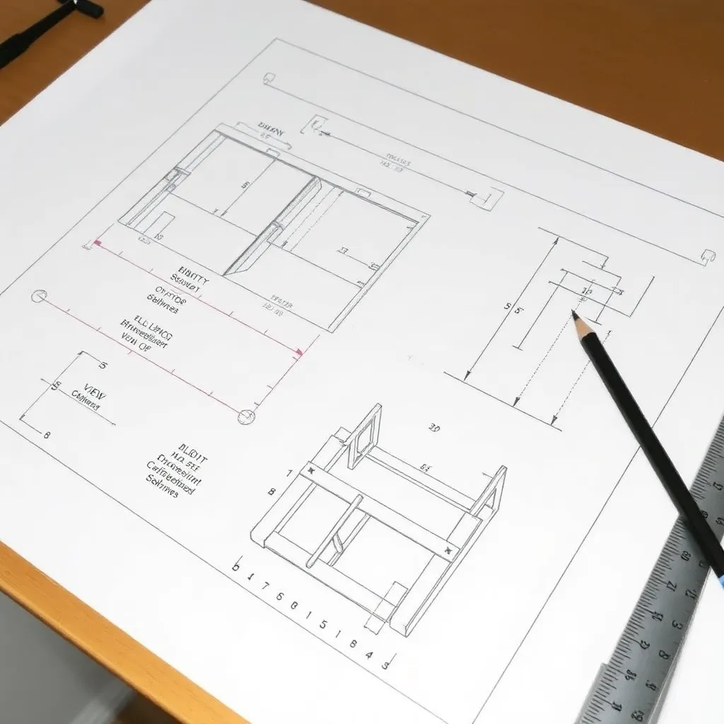
Most woodworking plans use one or more of these four view types:
Orthographic views (flat drawings):
- Front view — what you see facing the piece straight-on
- Top view (plan view) — looking straight down from above
- Side view — looking at the left or right end
- Back view — the rear face (shown when back details differ from front)
Plans place these views in a consistent arrangement: front view upper-left, top view lower-left (aligned below the front view), and right side view to the right of the front view. This arrangement is called “third-angle projection” (standard in the US and UK).
Section view — shows the interior of a piece by “cutting” through it. Identified by a cutting-plane line on the main view (a dash-dot-dash line with arrows indicating which direction you’re looking). The section view itself is labeled (SECTION A-A, SECTION B-B, etc.). Wood grain shown in section views always appears as diagonal hatching.
Milestone: You can identify which view you’re looking at and know which face of the piece it represents.
Step 3: Read Joinery Callouts
Goal: Understand how parts connect without having to guess from the drawing alone.
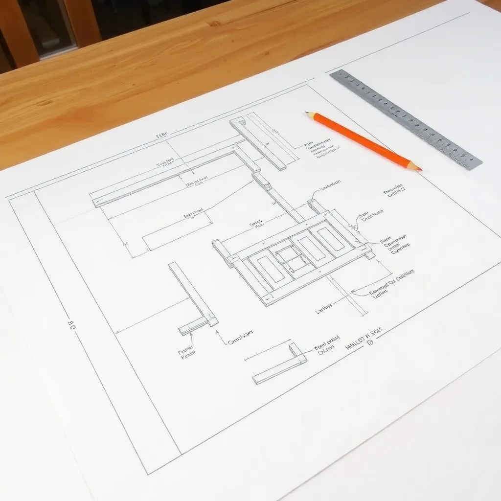
Standard joinery symbols and callouts:
Mortise and tenon: The mortise (the hole) is typically shown in the receiving piece as a dashed rectangle (dashed = hidden/interior feature). The tenon dimensions are called out separately: “⅜ × 1 × 2 TENON” means a tenon ⅜ inch thick, 1 inch wide, and 2 inches long.
Dado and rabbet: A dado (a groove that runs across the grain) is shown as two parallel dashed lines at the depth of the cut, with callout: “¾ WIDE × ⅜ DEEP DADO.” A rabbet (a step cut along an edge) is similar but at the edge.
Pocket screws: Shown as a circle with an X at the drilling angle, usually with a callout specifying the Kreg jig setting (material thickness) and screw length.
Dowels: Shown as a circle in the face view and as an oval in the edge view, with dimensions called out: “⅜ DIA × 1½ DOWEL.”
Biscuits: Small ellipse symbols at the joint location, usually labeled “#20 BISCUIT” or similar.
Dovetails: The tail profile is drawn in the front/end view with the exact angle shown (typically 1:6 for hardwoods, 1:8 for softwoods) and the number of tails specified.
Milestone: You can read a joinery callout and know exactly what joint to cut and its exact dimensions.
Step 4: Read an Exploded View
Goal: Understand how all parts of a project fit together before cutting anything.
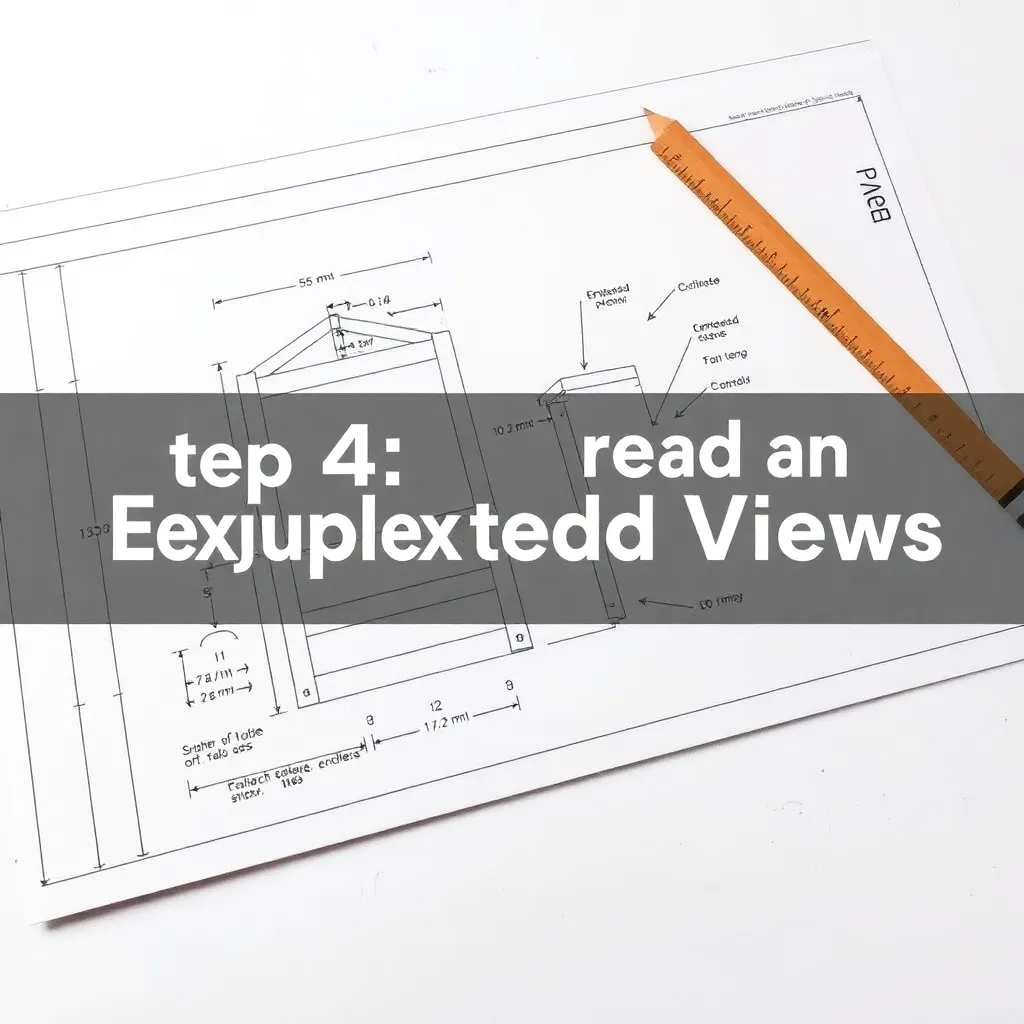
An exploded view shows all parts of an assembly separated and aligned along the axes along which they come together — as if the project were literally exploded apart while keeping each piece’s position in space. It’s the most useful view in any woodworking plan because it shows assembly sequence visually.
How to read it:
- Find the largest piece — this is usually the case, the top, or the main frame
- Find the parts that connect directly to it — these are the first assembly step
- Work outward from the center part by part
- Check that all pieces shown in the exploded view also appear in the cut list — missing from the list means the plan has an error
Parts are labeled with callout numbers (circled numbers pointing to each part) that correspond to the cut list or bill of materials. “1 — Side Panel (2 REQ’D)” means two side panels are needed, both identical.
Milestone: You can trace the entire assembly sequence from an exploded view before building a single piece.
Step 5: Read Hardware and Finish Callouts
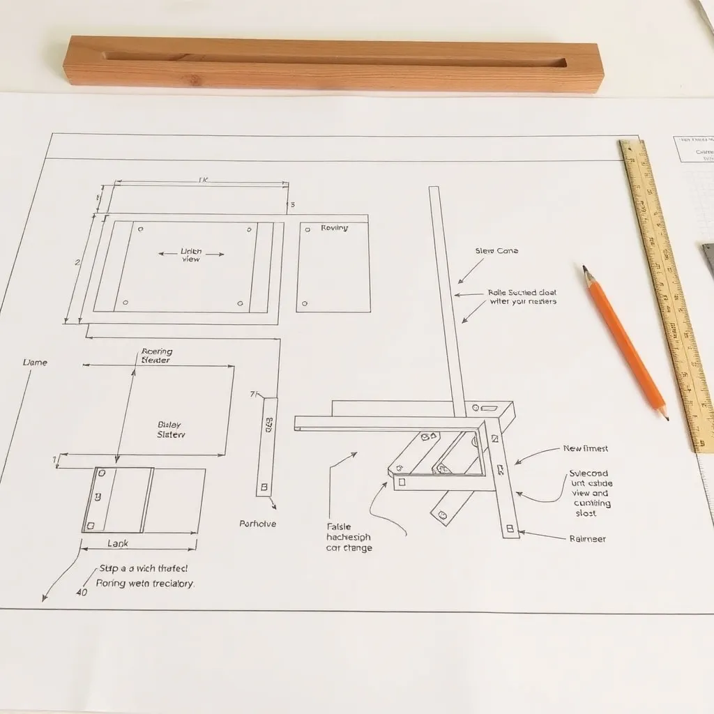
Goal: Know exactly what hardware to buy and where it goes before starting the build.
Screw callouts: Listed as length × diameter type. “2½ × #8 FH” means a 2½-inch number-8 flat-head screw. Common abbreviations: FH = flat head, PH = pan head, RH = round head, LH = lag hex (bolt-style lag).
Hinge callouts: “2 × BRASS BUTT HINGE” means two butt hinges made of brass. Piano hinge callouts include the length (“36 PIANO HINGE”). European hinge callouts include the cup diameter (“35mm EURO HINGE”).
Finish callouts: Usually in a notes section: “APPLY 2 COATS DANISH OIL, THEN 3 COATS WIPE-ON POLY” means exactly what it says. “SAND TO 220 BETWEEN COATS” means 220-grit sanding paper.
“TYP” (Typical): When a callout says “TYP,” it applies to all identical features — you don’t need a separate callout for each. “6 × #8 FH — TYP” on one screw location means every identical screw connection uses a 6-inch #8 flat head.
“REQ’D” (Required): Appears in the cut list — “4 REQ’D” next to a part description means you need to make four identical pieces.
Milestone: You can read the hardware callouts and build a complete shopping list before starting.
Step 6: Read Scale and Grid Drawings
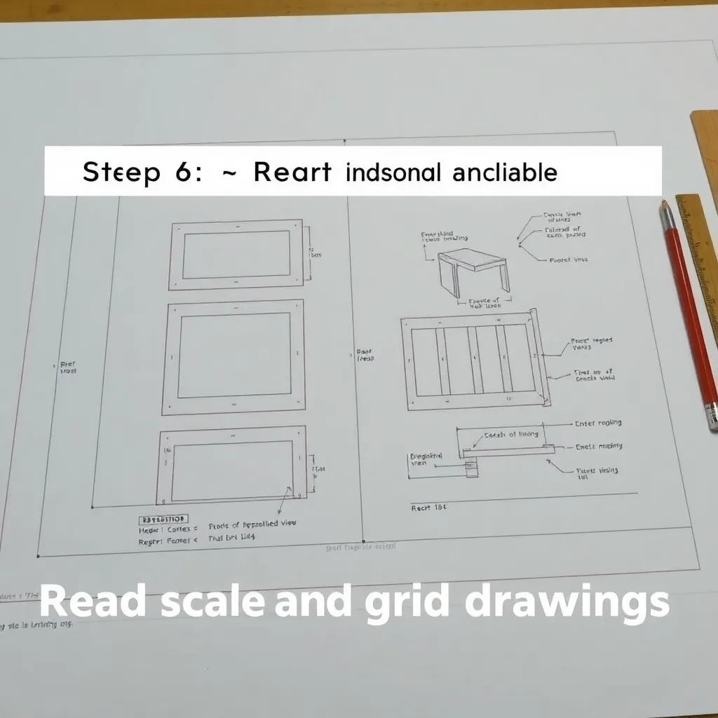
Goal: Transfer a scaled drawing to actual dimensions or full-size templates.
Some woodworking plans use scale drawings for curved parts (chair backs, cabriole legs, scroll profiles) where showing the actual size would require a page too large for the plan document. These are typically shown on a grid.
Scale notation: “1 SQUARE = ½ INCH” means each grid square represents ½ inch in the actual part. To transfer: draw a grid on paper (or on the workpiece itself) with ½-inch squares and copy the curve square-by-square. Alternatively, photocopy the drawing at the correct scale percentage to produce a full-size template.
1:1 plans (full size): Some professional plan sets include full-size paper patterns for curved parts — trace directly onto the workpiece and cut. These are labeled “FULL SIZE” or “1:1 SCALE.”
Centerline symbol (CL or ℄): Indicates the axis of symmetry — the part is symmetric about this line. Half-profile drawings are common for symmetric parts; you trace the half, flip the template, and complete the full shape.
Milestone: You can reproduce a scaled or full-size template from any plan drawing accurately.
Woodworking Plan Symbols FAQ
Do I need to understand all these symbols to start woodworking?
No — start with dimension lines (Step 1) and exploded views (Step 4). These two elements appear in every plan and give you the measurements and the assembly sequence. Joinery callouts and section views become necessary as projects get more complex (cabinets, furniture with fitted joints). Most beginner plans from quality sources are annotated clearly enough that you can build from the photos and cut list alone, using the drawings to clarify specific dimensions.
What does “NTS” or “NOT TO SCALE” mean on a plan drawing?
It means the view shown is schematic — useful for understanding the relationship between parts but not drawn to a consistent scale. Don’t measure off an NTS drawing to determine dimensions — use only the dimensioned callouts. NTS views are common for detail callouts (showing a close-up of a joint that’s too small to dimension accurately in the main view).
How do I read a cut list if I don’t have the right lumber width?
A cut list specifies the finished size of each piece, not the lumber size to buy. If the cut list says “1½ × 5½ × 36” (a 2×6 at 36 inches), you buy a 2×6 (which is actually 1½ × 5½) and cut it to 36 inches. If the finished width is larger than available lumber (for example, “12 wide” when 1×12s are only 11¼ actual), you need to glue two narrower boards together — the plan should note this in the assembly instructions.
What’s the difference between a face view and an end view?
A face view (also called a front elevation) shows the wide face of a board — what you see when looking straight at the flat surface. An end view (also called an end elevation or cross-section) shows the narrow end of the board — the end grain face. End views are often used to show joinery details like mortises and dadoes that aren’t visible from the face.

“DIY woodworking enthusiast who started with zero experience and a YouTube tutorial.
I build simple, practical projects for my home and share free plans
so other beginners can skip the guesswork.If I can build it, you can too.”